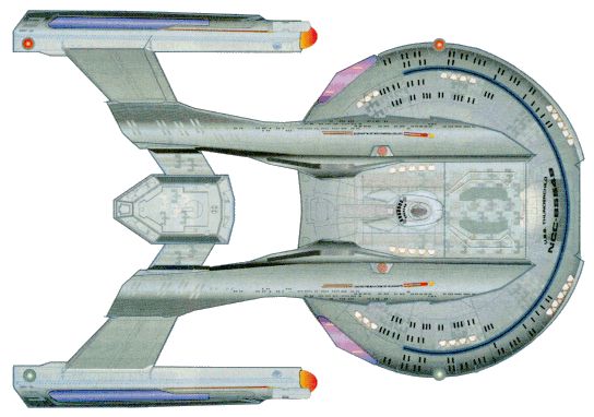
Akira-Class Heavy Cruiser
UNITED
FEDERATION OF PLANETS: STARFLEET DIVISION
Advanced Technical Specifications for the Akira-Class Production Vehicle
![]()
| Accommodation:
500 (100 Officers - 400 Enlisted Crew) Classification:
Heavy Cruiser [Defensive/Explorer/Diplomatic] Funding
for Akira Class Development Project Provided by:
Advanced Starship Design Bureau; United Federation of Planets Defense
Council. Developed by Yoyodyne
Propulsion Systems, LTD. Development
Project Started: 2353 Production
Start Date: 2364 Production
End Date: Still in
Production Current
Status: In Service |
Locations
of Akira-Class Construction:
Current
Starship Identification and Registration Numbers:
|
Pursuant to Starfleet Exploration Directives 902.3 & 914.5, Starfleet Defense Directives 138.6, 141.1 & 154.7, and Federation Security Council General Policy, the following objectives have been established for an Akira Class Starship:
Replace Excelsior, Ambassador, and New Orleans class Starships as the primary instrument of Federation deep-space defense.
Provide a mobile platform for a wide range of ongoing scientific and cultural research projects.
Provide autonomous capability for full execution of Federation defensive, cultural, scientific, and explorative policy in deep space or border territory.
Serve as a frontline support vehicle during times of war and emergencies.
Provide a mobile platform for testing and implementation of mission-specific or new technology of any kind.
Length: 464.43
meters
Width: 316.67 meters
Height: 87.43 meters
Weight: 3,055,000 metric tons
Cargo capacity: 47,254 metric tons
Hull:
Duranium-Tritanium composite with micro-fiber reinforced ablative armor
over critical compartments.
Number
of Decks: 18 Total, 17 Habitable.
Editor's Note: History written by Steve Mallory - based on information found in Star Trek: First Contact, Star Trek: Voyager, Star Trek Technical Manual, Star Trek: The Next Generation Technical Manual, Star Trek: Deep Space 9 Technical Manual, and Star Trek: The Magazine. The style of the history is based on histories presented in the Startrek Spaceflight Chronology by Stan Goldstein, Fred Goldstein, and Rick Sternbach. Please keep in mind that this is a history developed based on canon information presented in various sources and filled in with logical conjecture.
The Akira Class starship entered service in 2364 and has quickly become the pride of Starfleet’s next generation of starships. Akira Class vessels are part of the new belief that smaller, faster, more maneuverable Starships are needed to better serve Starfleet's, and, by extension, the Federation's needs.
Initial production of the Akira class began at the ASDB Integration Facility, New Aberdeen Fleetyards, Aldebaran, and has since expanded to include the ASDB Integration Facility, Utopia Planitia, Mars where nearly 15 of these vessels enter service each year, and the newly revamped Atlas V Assembly Facility, Deneb V along with the Antares Fleetyard.
Unlike many larger starships of its development era, with saucer separation as a prerequisite, Akira Class vessels to date cannot separate into two vessels. As a result, the Akira Class no longer has the twin hull design that has been seen in vessels such as Excelsior, New Orleans, Galaxy and Ambassador Classes. This means that the primary hull and the engineering hull are no longer separate, with no "neck" section. While this division of Saucer and Stardrive has been blurred, it does allow the Akira Class to make a smoother, less polluted entry into subspace during Warp. Also, because of this "no stardrive" design, the surface between the two hulls has a much more gradual descent and streamlined appearance; the dorsal mid-ships section, which slopes up where the two hulls connect. The Akira spaceframe appears very similar in design to that of an ancient earth sailing boat known as a Catamaran. With the Nacelles parallel to the main hull, they can be more adequately protected by the primary and secondary shield generators with only a minimal loss in shield efficiency.
The final armaments for the Akira
Class were finalized during the end of the primary development phase
and implemented during the vessel's first production contract at both
ASDB Facilities. Realizing that relations with the Cardassians was
going to deteriorate before they improved, and the looming presence of
a Borg incursion, Starfleet requested that a portion of the new Akira’s
be refitted with more weaponry and upgraded shields. The resulting Akira
class mounted no less than 15 Photon torpedo tubes spread between 3
launchers scattered around the vessel [2 located on the Aft sail, and 1
mounted on the ventral portion of the vessel just above the main
deflector].
Heavily armed, the design philosophy for the Akira class created lessons later utilized in the Defiant Project, especially the early “Torpedo Gunboat” design that was later scrapped in favor of the current design. A Combined Forward/Aft torpedo bay is located both along the Aft Dorsal "Sail" portion of the hull, while a second set of forward launchers are located just under the nose of the ship. Combined with the Type X phaser array, the current Akira class is heavily armed, and in raw torpedo firepower, could return fire - torpedo for torpedo, with the vaunted Galaxy / Nebula Class launchers.
With the Saber class designed to replace the Miranda and her sister classes (Soyuz, etc) of starships on internal police patrols, and with the Merced and New Orleans Class functioning adequately in the role of Mission-Specific Frigate, it was a waste of scientific resources to assign those classes to defensive patrols on the Cardassian Frontier where they were clearly outgunned against Galor class Battlecruisers. Akira class starships were outfitted with a full-fly through hangar on deck 12 from which no more than 40 Kaneda Class fighters could be launched, combined with the 3 photon torpedo launchers and 6 Type X phaser array’s standard on the Akira class, gave the carrier impressive sublight combat capabilities and could stand toe-to-toe against even the most determined Cardassian attack.
Starfleet Command issued a request to the major fleet yards in 2353 for a design and engineering specifications for a new Heavy Cruiser to supplant the Excelsior and Ambassador Class starships as the primary instrument of Federation defense. The production contract was awarded to the New Aberdeen Fleetyards in the Aldebaran system, with the now infamous Yoyodyne Propulsion Systems as the primary engineering firm. Starfleet Command requested, specifically, a smaller, more heavily armed and most importantly quicker constructed vessel than the Ambassador Class, without sacrificing firepower or shielding.
This stipulation was no small request, as the Ambassador Class vessel was by far the most heavily armed and armored vessel Starfleet could field at the time. She was also the largest class in Starfleet history, until the launch of the Galaxy Class, and was also the most crew intensive in service.
The first test hull, now dubbed the USS Akira by the development team after the project name, was laid in 2356 and basic compartmentalization was completed two years later, when the Consolidated Fusion Inc. M/ARA core and nacelle structure was installed. Due to the unique configuration of the hull, along with the layout of the deckspace, which was unique compared to the Ambassador, Merced, Excelsior, and most other vessels of its classification, the standard General Propulsion Mark VI Impulse Plant and Malkinalis 8.5 M/ARA warp core used in the upgrades on the Excelsior Class and the Merced class Frigate, the standard Impulse and M/ARA configuration at the time, had to be abandoned (as it would later with the Steamrunner Project). The Akira hull, assigned the registry NX 62497, launched from the New Aberdeen fleetyards in the spring of 2358 for warp core testing.
At the time of her warp core and engine testing, she was unarmed, with plans for Type VIII phaser arrays planned for deployment aboard the class, along with two photon torpedo launchers. The USS Spann [Excelsior Class - NCC 3995] and the USS Zachary [Miranda Class - NCC 2311] escorted the Akira hull from her berth to deep space for trials. The Akira hull did not reach Warp 3 before the safety cutoffs dropped the hull from warp - under emergency power, she was towed back to the New Aberdeen Fleetyards for review. Simulations could not determine the exact cause of the error. Two more tests gave the same results - the hull was decompartmentalized and the structural framework went into review.
After this in-depth analysis, the Akira project design team rejected Consolidated Fusion Inc.’s M/ARA and Impulse engine design, after three Time trials utilizing the CFI M/ARA configuration, strong and potentially damaging hull stress fractures occurred within the main structural network. It was determined that the warp harmonics generated by the Core was the cause of the damage, and the CFI M/ARA unit was scrapped (the design was later picked up by the Steamrunner project). The Project Akira hull, along with its two half-completed sister ships were put into cold storage for nearly 5 years.
It wasn't until the development and widespread utilization of technologies found in the TPG Matter/Anti-Matter Reaction Drive, by Theoretical Propulsion Group, that the Akira Project was revived. The new warp cores for the Galaxy Class utilized the latest in Plasma Induction and Warp Harmonic Control to create a stable, powerful warp core, and with Project Akira's unique hull configuration, was a must if the vessel was to see active duty. Project Akira took a new RamJet Mark I off of the assembly lines, updated it with the technologies developed by Theoretical Propulsion Group, which meant they had to abandon the traditional vertical warp core, instead using the horizontal mounting reminiscent of the Constitution-Refit class. The resulting configuration completely eliminated the shearing forces created by the warp core, while also reducing deuterium usage by nearly five percent in comparison to the original configuration.
To increase the combat efficiency of the Akira class, Yoyodyne propulsion systems lead designer Alex Jaeger proposed the addition of two additional torpedo launchers, each armed with 5 tubes, to be located both in the dorsal and ventral portion of the main dish hull and fixed to the forward firing arc. This would give the Akira class tremendous firepower in the forward firing arcs and could overwhelm even the vaunted shielding of the Cardassian Galor class battlecruiser, a vessel that clearly outgunned the Akira class before the redesign, and was a match for both the Excelsior and Ambassador class starship. With a total of 15 torpedo tubes, the Akira Class earned the distinction of being the first vessel in Starfleet history to rely on the Photon Torpedo, not the Phaser, as her primary armament. Further, the phasers were upgraded from Type VIII to Type X in mid-production - no Akira Class vessel ever entered service officially with anything less than a Type X phaser array.
NX 62497
left the New Aberdeen Fleetyard Facility in 2363 for final Impulse
engine stress testing near Wolf 359, flanked by the USS Ottawa [Excelsior
Class - NCC 3299] and the USS Unification [Ambassador
Class - NCC 19995]. Stress tolerances were well within expected levels,
and the hull returned to Aldebaran for final interior compartment
completion. The hull, named the USS Akira, had final
compartmentalization completed on March 15, 2364 and took its final
shakedown cruise through April 29, 2364 when she arrived at Sol system
for its official launch. By the time the USS Akira entered into service
in 2364, her sister ship, the USS Bejing NCC 62498
was nearing completion at New Aberdeen, with no less than 10 more hulls
being prepared for construction at both the Utopia Planitia Fleetyards
and the New Aberdeen Fleetyards.
At the height of production, the New Aberdeen Fleet Yards, the Balkinur
Cosmodrome and the Atlas V Fleetyards of Deneb V were producing Akira
Class vessels. Additional construction contracts were issued
to the larger Utopia Planitia and the Antares V Fleetyards.
The USS Akira and her sister vessels were immediately dispatched to both the Romulan Neutral Zone and along the Federation/Cardassian Border. The Akira class was favored by many a Captain for being a durable and dependable vessel, thanks in part on being built using standardized Federation components already tested and deployed successfully in no less than three classes of vessels. With the advent of the Borg threat, along with increased tension between the Federation and the Cardassians, the Akira class was designated to more and more defense and patrol related duties, leaving the Nebula class to serve as the Diplomatic and Exploratory arms of Starfleet. Further, the deployment of the Kaneda Class Space Superiority Starfighter, mounting Micro-torpedoes and Type VI Shuttle class Phaser Emitters, extended the range of the Akira class and provided unprecedented sublight combat capabilities and intelligence gathering capabilities.
With Excelsior Class vessels taking staggering losses, and clearly outgunned when faced against Dominion Battleships, Starfleet reissued production contracts for the Akira class. It was a proven design, heavily armed for its size, and was well-suited for combat against Dominion Threat vessels. Production of the Akira class fell on Antares V Fleetyards, Utopia Planitia, the Copernicus Fleetyard, and the newly revamped New Aberdeen Fleetyards, where production continues to this day. Several small modifications have since been made to the refit specifications on the Akira Class, including the addition of EMH technology in Sickbay and Ablative Armor to the nacelle and aft sail assembly, to further increase combat survivability.
After the war, most Akira Class vessels had their Fighter Wings transferred to fixed orbital facilities or ground based Starfleet or Allied Facilities to allow for additional cargo space and the addition of modular laboratories installed into the unused Hangar space. This gave the majority of the Akira class laboratories and, most of all, doubled the normal loadout of sensor probes, making the class a premier exploration vehicle with half of the crew and construction costs of a Galaxy or Sovereign Class Starship.
General Overview: Primary operational control of the Akira Class is provided by the Main Bridge, located at the top of the primary hull. It is located on Deck 1. The Main Bridge directly supervises all primary mission operations (with the exception of the Flight bay and assorted craft) and coordinates all departmental activities.
The Main Bridge is a highly restricted area; only Beta-Two security clearance personnel (Officers with the Rank of Ensign or Higher) and authorized bridge personnel are allowed on the bridge. All bridge officers carry a type II phaser.
The Main Bridge is an ejectable module, allowing for a wider variety in mission parameters.
Layout: The new primary Bridge configuration is a combination of the new Soveriegn Class with the Intrepid Class starship. The central area of the Main Bridge provides seating and information displays for the Captain and two other officers. The Captain’s Chair is raised from the rest of the Bridge Officers, to that of the Surrounding level which includes Tactical and Operations. The two Officer seats are equipped with fully programmable consoles for a variety of uses.
Directly fore of the command area is the Flight Control Officer, who faces the main viewer. The FCO is equipped with a console that proceeds around an almost one hundred and eighty degree angle.
At the very front of the bridge chamber is a large viewscreen. This main viewer performs all the standard duties expected of it. However, the viewscreen is not always activated like most other Starships. It is a full Holographic display, that can be activated upon request. When the screen is not active, a standard bulkhead is present. This addition was made into the Akira Class, so that Star-Field syndrome among Bridge officers would be stopped. Too many officers became hypnotized during warp.
Aft and to the left of the command area is an elevated platform on which is located the tactical/security control station (comprised of two consoles, one for tactical, and one for security, located directly behind tactical and along the back of the bridge area). These consoles are to the left side of the Captain’s Chair, no longer in the direct middle.
To the Captain's right is the Operations manager's console. Identical in size and design to the Tacitcal/Security station, the Operations manager is located closer to the bridge engineering station rather than close to the front of the bridge. The Operations Panel, due to the tremendous amount of sensitive information found there, has security protocols as stringent as the TAC consoles. Directly aft of the Ship Operations Console is the Mission Operations Console, for use during Away team missions.
Also located on the platform, against the aft wall of the bridge, is a large master systems display monitor, similar to the one in main engineering. All relative ship information (such as damage, power distribution, etc.) is displayed on the cutaway image of the Akira Class. This monitor can be used to direct ship operations and can be configured for limited flight control if necessary.
Against the port side walls of the main bridge are the consoles for Science and others that are programmable for a multitude of functions. There are two Science consoles with Science 2 being a fully programmable multi-mission Console. Science I, which is the primary science console. Science I has priority links to Conn, Ops, Computers, and Tactical.
Science II is the ASO's (Assistant Science Officer's) console, which can be used by any personnel. Science II has access to all science, navigational, sensor, and communications systems. Science II can be configured to operate in tandem with Science I, although security links and all other non-science data is withheld from Science II. Science II usually works independently of Science I.
Against the starboard wall of the main bridge is the large engineering console. This has a smaller cutaway diagram of the Akira Class, which displays all engineering-relevant data and shows warp fields and engine output. This console also has priority links to the computers, the WPS (Warp Propulsion System), the IPS (Impulse Propulsion System), navigation, SIF, and IDF. Although usually unattended, the Chief Engineer can bring this console to full Enable mode by entering voice codes and undergoing a retinal scan. Directly aft of this console is the Engineering II console, which is fully programmable to run any Secondary Console function, including Sciences, Medical, Operations, Limited Helm control, or Security.
This console, as does every console on the bridge, also has the hand-input sub-console for use in setting the auto-Destruct of Akira Class. The auto-destruct sequence follows Standard Starfleet security procedures which can be accessed via any secured Memory Alpha ODN connection.
There are two turbolifts on the bridge that can handle normal transit around the Akira Class. There is also an emergency ladder that connects the bridge to Deck two. There is also one door, on the aft platform of the bridge, that leads to the Conference Room, which is directly aft of the Main Bridge. Other connected rooms to the Main Bridge include the Captain's Ready Room.
There are No escape pods connected to the bridge. Pods are located on all decks below Deck three. For more information on the specifications of the Lifeboats, please refer to section 11.2. Two pods are reserved for the top four officers in the chain of command on the Akira Class, because they are the last four to leave the ship. These are located on Deck two. As the number of experienced Captains dwindles in Starfleet, the notion of a Captain going down with his ship has been abolished. If the ship is abandoned, the top four officers in the chain of command will wait until everyone else is off the ship, opt to arm the auto-Destruct (not always necessary, but there if needed), and then leave in the two escape pods.
This multi-room department is located in a restricted area on deck 15. Within it are the entrances to the phaser range, the Brig, the torpedo/probe magazine, the auxiliary weapon control room and to the Ship's Armory, as well as the Chief Tactical Officer's office.
The CTO's office is decorated to the officer's preference. It contains a work area, a personal viewscreen, a computer display, and a replicator.
Brig: Located on deck 15, the brig is a restricted access area whose only entrance is from within the Security department. The Akira class vessel has 10 double occupancy cells, which contain beds, a retractable table and chairs, a water dispenser, and a toilet. The cells are secured with a level 10 forcefield emitter built into each doorway.
Ship's Armory: This room is located in a restricted area on deck 15 and is under constant guard. The room is sealed with a level 10 forcefield and can only be accessed by personnel with Alpha 3 security clearance. Inside the armory is a work area for maintenance and repair of phasers as well as multiple sealed weapon lockers. The Akira Class carries enough type-I and type-II phasers to arm the entire crew. Type-III phaser rifle and the new compression phaser rifles are available as well, but only in enough numbers to arm approximately 1/3 of the crew. Heavy ordinance is available in limited numbers.
Torpedo/Probe Magazine: This restricted area on deck 9 is for storing unarmed photon torpedoes, quantum torpedoes (if the mission dictates), and science probes I - VI (VII - X if mission dictates). Also stored here are the components for manufacturing new photon torpedo as well as the equipment to put it all together. This room is also accessed by the loading mechanism for the torpedo launchers.
2.3
TACTICAL INFORMATION CENTER
![]()
This is the nerve center for Flight Operations, conducting combat operations utilizing the Akira's Spacefighter Wing, and sifting through the numerous sensor plots and intelligence gathered by the starfighters. A large room, the TIC is twice as large as the Ship's bridge, and is fully manned through all duty shifts. The TIC is typically commanded by the Second Officer.
TIC General Overview: Primary Flight Operational Control of the Akira Class is provided by the TIC, located on decks A and B of the aft sail area. The TIC directly supervises all primary and secondary Flight Operations and coordinates all Flight, Search and Rescue, and Fighter-based activities.
The TIC is a highly restricted area; only Beta-One security clearance personnel and authorized TIC personnel are allowed on the bridge.
Layout: The new TIC configuration is unique to the Akira class, and closely resembles a Starbase Bridge/Operations Center. The central area of the TIC provides a large holographic display, viewable from the entire TIC. Attached to the holoprojector are the TIC Supervisor, and his two executive officer's consoles. Identical in size and design to the bridge Mission Operations console, these consoles are the heart of the TIC. All information pertaining Flight Operations, Maintenance Schedules, Intelligence Gathering, and whatever operations the TIC is currently engaged with, can be accessed by these consoles.
Directly fore of the holoviewer are the Flight Ops Officers. The 8 FO Officers are equipped with a console that proceeds across the entire Foredeck, each with access to visuals of Flight Decks, Fightercraft, Shuttlecraft, along with Helm and Science information from the bridge. The FO's are in charge of maintaining full flight operation efficiency.
Aft and to the left of the command area is an elevated platform on which is located the tactical/security control station (comprised of two consoles, one for tactical, and one for security, located directly behind tactical and along the back of the TIC area). Each console is manned by 2 officers, and their role is to keep the TIC CO appraised of missions objectives in combat operations, should the Akira enter combat, along with the status of Flight Operations in the Combat Zone.
Against the Starboard wall of the TIC, on a raised platform, is a large master systems display monitor, similar to the one in main engineering and identical to the display monitor on the Bridge. All relative ship information (such as damage, power distribution, etc.) is displayed on the cutaway image of the Akira Class. This monitor can be used to direct ship operations and can be configured for limited flight control if necessary.
In front of the TIC master systems display monitor is a large engineering console. This has a smaller cutaway diagram of the Akira Class, which displays all engineering-relevant data and shows warp fields and engine output. This console also has priority links to the computers, the WPS (Warp Propulsion System), the IPS (Impulse Propulsion System), navigation, SIF, and IDF, and is a backup console for the Main Engineer to access Engineering subroutines and protocols away from Main Engineering. Although usually unattended, the Chief Engineer can bring this console to full Enable mode by entering voice codes and undergoing a retinal scan. In its typical configuration, the TIC Engineers Mate maintains work schedules and verifies repair, maintenance and refit programs for the various starfighters and shuttlecraft aboard the Akira Class vessel.
Against the port side walls of the main bridge are the consoles for Science and others that are programmable for a multitude of functions. There are two fully programable multi-mission consoles. These consoles have access to all science, navigational, sensor, and communications systems. These consoles are typically configured for Intelligence Gathering and collating data retrieved by Shuttlecraft or Fightercraft.
There is also an emergency ladder that connects the TIC to Lower Engineering. There is also one door, on the aft platform of the bridge, that leads to the TIC Space Wing Briefing Room, which is directly aft of the TIC.
Located on Deck 14, Main Engineering is the ‘heart’ of the ship, comparable to the bridge as the ‘brain’. It has access to almost all systems aboard the starship, and manages repairs, power flow, and general maintenance.
Entrance to the primary engineering spaces is provided by two large blast doors, a pair each on decks 13, 14, and 15, that can be closed in cased for internal or external security reasons, as well as in case of emergencies.
Just inside of the doors on deck 14 - Main Engineering - is an observation area where technicians monitor various systems of the ship. Also in that area, is a floor-mounted situational display similar to the Master Systems Display found on the Bridge. Affectionately referred to as the ‘pool table’, the Chief Engineer can use the display to more easily get a broad view of the situation with just a glance.
Farther in from observation area is the warp core and main control systems. Circular in shape, the room is an outgrowth of the Galaxy Class design, but exceedingly functional to save space inside the ship. Usable consoles are mounted on every piece of ‘real estate’ around the circumference of the room and provide primary control access for the engineers and technicians. Additionally, there are numerous ladders and access panels to Jefferies tubes, leading throughout the starship - the Sovereign Class being the first series of starship to take full advantage of these access spaces for more than extraordinary maintenance. The technical complexity of the starship dictates the use of these spaces to maintain peak efficiency and affect proper repairs.
Off to the starboard side of Main Engineering is the Chief Engineer’s Office, which is equipped with a diagnostics table, assembly and repair equipment, a small replicator, and a personal use console with built-in private viewscreen.
In
the center of Main Engineering is the Matter/Anti-Matter Assembly
(M/ARA). This is where primary power for the ship is generated inside
the Matter/Anti-Matter Reaction Chamber (M/ARC). This system is checked
on a regular basis due to its importance to the ship. Access to the
warp core is restricted, with a front port to get to the Dilithium
matrix as well as an over side port for access to the warp plasma
conduits.
A second tier rings the second level of Main Engineering on deck 13.
Two small single-person elevators, as well as a ladder on the opposite
end, provide access to this catwalk. Controls for the various
Fusion Power Plants, along with the Impulse Engines, are monitored from
this deck.
A lower tier runs below Main Engineering on deck 15. Damage Control Teams are mustered here, as well as internal ship maintenance teams. Numerous consoles and replicators line this section, serving as auxiliary consoles for Main Engineering, along with providing engineering research space and secondary computer core support.
Access
to the Jeffries Tubes is provided in various places on both the First,
Second and Third Tier of the Engineering Spaces.
Typical crew compliment in Main Engineering consists of twenty
engineers and forty technicians of various grades. During Red or Yellow
Alert, that number is increased.
Phaser array arrangement: Two dorsal phaser arrays on the primary hull, extending from just aft of the bridge to almost midway around the saucer section. The arrays converge to intersect at the bow of the ship, giving them an almost oval appearance. Two ventral phaser arrays on the primary hull, extending from the very back of the primary hull almost to the bow. These arrays also converge gradually as they approach the widest part of the primary hull, converging near the bow. Two phaser arrays are located on or near the aft sail covering the rear firing arc.
Phaser Array Type: The Akira Class utilizes the Type X array system. The seven arrays are all type X, the new standard emitter. Each array fires a steady beam of phaser energy, and the forced-focus emitters discharge the phasers at speeds approaching .986c (which works out to about 182,520 miles per second - nearly warp one). The phaser array automatically rotates phaser frequency and attempts to lock onto the frequency and phase of a threat vehicle's shields for shield penetration.
Phaser Array Output: Each phaser array takes its energy directly from the impulse drive and auxiliary fusion generators. Individually, each Type X emitter can only discharge approximately 5.1 MW (megawatts). However, several emitters (usually two) fire at once in the array during standard firing procedures, resulting in a discharge approximately 10.2 MW.
Phaser Array Range: Maximum effective range is 300,000 kilometers.
Primary purpose: Assault
Secondary purpose: Defense/anti-spacecraft/anti-fighter
Arrangement: Three fixed-focus torpedo launchers, one located just above the main deflector dish and another at the bow of the primary hull along with a third launcher within the main sail. These launchers are the second generation of automated, high-speed launchers originally developed and found on the New Orleans and Saber Class (and later seen aboard Excelsior Class Starships as part of their refit schedule) starships and each launcher is armed with 5 tubes per launcher, giving the Akira Class the ability to launch up to fifteen torpedoes in a single salvo. The third generation of this launcher has seen deployment aboard the Sovereign Class and Norway Class.
Type: Mark XXV photon torpedo, capable of pattern firing (sierra, etc.) as well as independent launch. Independent targeting once launched from the ship, detonation on contact unless otherwise directed by the Chief Tactical Officer or TIC Weapons Officer.
Payload: The ship can carry a maximum of 375 torpedoes.
Range: Maximum effective range is 3,000,000 kilometers.
Primary purpose: Assault
Secondary purpose: Anti-spacecraft
Type: A symmetrical subspace graviton field. This type of shield is fairly similar to those of most other Starships. However, besides incorporating the now mandatory nutation shift in frequency, the shields alter their graviton polarity to better deal with more powerful weapons, such as the neutron-carbide beams of Tamarian vessels. During combat, the shield sends data on what type of weapon is being used on it, and what frequency and phase the weapon uses. Once this is analyzed by the tactical officer, the shield can be configured to have the same frequency as the incoming weapon - but different nutation. This tactic dramatically increases shield efficiency.
Output: There are sixteen shield grids on the Akira Class, and each one generates 186 MW, resulting in a total shield strength of 2976 MW. However, during normal combat operations, only 10 of the 16 shield generators are activated, with the remaining 6 generators serving as the emergency shield system. This means that, in normal combat operations, the Akira class has a rated shield strength of 1860MW. The power for the shields is taken directly from the warp engines and impulse fusion generators. If desired, the shields can be augmented by power from the impulse power plants. The shields can protect against approximately 36% of the total EM spectrum (whereas the standard Galaxy Class Starship's shields can only protect against about 23%), made possible by the multi-phase graviton polarity flux technology incorporated into the shields.
Range: The shields, when raised, stay extremely close to the hull to conserve energy - average range is ten meters away from the hull.
Primary purpose: Defense from enemy threat forces, hazardous radiation and micro-meteoroid particles.
Secondary purpose: Ramming threat vehicles.
Number of computer cores: Two; The primary core one occupies space on decks 7, 8 and 9 far astern. The secondary, emergency core is much smaller than the first and is located adjacent to Environmental Control on Deck 16.
Type: The updated Computer cores found on the Akira class are newer versions of the Galaxy Class Isolinear Processing cores. The system is powered by a smaller, regulated EPS conduit directly from the warp core. Cooling of the isolinear loop is accomplished by a regenerative liquid nitrogen loop, which has been refit to allow a delayed-venting heat storage unit for "Silent Running." For missions, requirements on the computer core rarely exceed 45-50% of total core processing and storage capacity. The rest of the core is utilized for various scientific, tactical, or intelligence gathering missions - or to backup data in the event of a damaged core.
Acronym for Library Computer Access and Retrieval System, the common user interface of 24th century computer systems, based on verbal and graphically enhanced keyboard/display input and output. The graphical interface adapts to the task which is supposed to be performed, allowing for maximum ease-of-use. The Akira Class operates on LCARS build version 5.2 to account for increases in processor speed and power, and limitations discovered in the field in earlier versions, and increased security.
Access to all Starfleet data is highly regulated. A standard set of access levels have been programmed into the computer cores of all ships in order to stop any undesired access to confidential data.
Security levels are also variable, and task-specific. Certain areas of the ship are restricted to unauthorized personnel, regardless of security level. Security levels can also be raised, lowered, or revoked by Command personnel.
Security levels in use aboard an Akira Class are:
Note: Security Levels beyond current rank can and are bestowed where, when and to whom they are necessary.
The main computer grants access based on a battery of checks to the individual user, including face and voice recognition in conjunction with a vocal code as an added level of security.
All Starfleet vessels make use of a computer program called a Universal Translator that is employed for communication among persons who speak different languages. It performs a pattern analysis of an unknown language based on a variety of criteria to create a translation matrix. The translator is built in the Starfleet badge and small receivers are implanted in the ear canal.
The Universal Translator matrix aboard an Akira Class starships typically consists of well over 100,000 languages and increases with every new encounter.
Type: RamJet Mark 1 Standard Matter/Anti-Matter Reaction Drive, developed by RamJet Propulsion. Information on this Warp Drive can be found in any Starfleet Library or Omnipedia.
Normal Cruising Speed: Warp 7
Cruising Speed as pursuant to Warp Limitations, as a cause of subspace pollution: Warp 5
Maximum Speed: Warp 9.8 for 12 hours
Note: Vessels equipped with the RamJet Mark 2 series M/ARA Drive System no longer have the maximum cruising speed limit of Warp 6.3, thanks to innovations discovered and utilized in the General Electric Type 8 M/ARA Warp Drive outfitted in the new Sovereign Class Starship. Pursuant to Starfleet Command Directive 12856.A, all Starships will receive upgrades to their Warp Core system to prevent further pollution of Subspace. To date, all vessels currently in service have received these upgrades.
Type: Standard Akira Class mass drivers developed and built by HighMPact Propulsion. Output is comparable to Ambassador Class.
Output: Each engine (there are two impulse engines) can propel the Akira Class at speeds within the area known as Standard impulse operations. These speeds are limited to a maximum speed of .25c, with each engine working at .125c, due to time dilation problems. Quarter impulse is rated at .0625c, half impulse being .125c and full impulse is rated at .25c or 1/4th the speed of light.
Type: Standard Version 4 magnetohydrodynamic gas-fusion thrusters, identical to thrusters deployed on the Ambassador Class starship. There are 24 of these thrusters spread across the primary hull to facilitate precise movement.
Output: Each thruster quad can produce 4.2 million Newtons of exhaust.
6.0
UTILITIES AND AUXILIARY SYSTEMS
![]()
A standard Akira Class main deflector dish is located along the ventral portion of the Akira Class's primary hull, and is located just forward of the primary engineering spaces. Composed of molybdenum/duranium mesh panels over a tritanium framework (beneath the Duranium-Tritanium hull), the dish can be manually moved twelve degrees in any direction off the ship's Z-axis. The main deflector dish's shield and sensor power comes from two graviton polarity generators located on deck 17, each capable of generating 128 MW, which can be fed into two 550 millicochrane subspace field distortion generators.
Type: Multiphase subspace graviton beam, used for direct manipulation of objects from a submicron to a macroscopic level at any relative bearing to the Akira Class. Each emitter is directly mounted to the primary members of the ship's framework, to lessen the effects of isopiestic subspace shearing, inertial potential imbalance, and mechanical stress.
Output: Each tractor beam emitter is built around three multiphase 15 MW graviton polarity sources, each feeding two 475 millicochrane subspace field amplifiers. Phase accuracy is within 1.3 arc-seconds per microsecond, which gives superior interference pattern control. Each emitter can gain extra power from the SIF by means of molybdenum-jacketed waveguides. The subspace fields generated around the beam (when the beam is used) can envelop objects up to 920 meters, lowering the local gravitational constant of the universe for the region inside the field and making the object much easier to manipulate.
Range: Effective tractor beam range varies with payload mass and desired delta-v (change in relative velocity). Assuming a nominal 15 m/sec-squared delta-v, the multiphase tractor emitters can be used with a payload approaching 116,380,000,000 metric tons at less than 2,000 meters. Conversely, the same delta-v can be imparted to an object massing about one metric ton at ranges approaching 30,000 kilometers.
Primary purpose: Towing or manipulation of objects
Secondary purpose: Tactical; pushing enemy ships into each other.
Number of Systems: 12
Personnel Transporters: 4 (Transporter Rooms 1-4)
Max Payload Mass: 900kg (1,763 lbs)
Max Range: 40,000 km
Max Beam Up/Out Rate: Approx. 100 persons per hour per Transporter
Cargo Transporters: 4
Max Payload Mass: 800 metric tons. Standard operation is molecular resolution (Non-Lifeform).
Set for quantum (lifeform) resolution: 1 metric ton
Max Beam Up/Out Rate (Quantum Setting): Approx. 100 persons per hour per Transporter
Emergency Transporters: 4
Max Range: 15,000 km (send only) [range depends on available power]
Max Beam Out Rate: 200 persons per hour per Transporter (800 persons per hour with 4 Emergency Transports)
7.0
SCIENCE AND REMOTE SENSING SYSTEMS
![]()
Long range and navigation sensors are located behind the main deflector dish, to avoid sensor "ghosts" and other detrimental effects consistent with main deflector dish millicochrane static field output. Lateral sensor pallets are located around the rim of the entire starship, providing full coverage in all standard scientific fields, but with emphasis in the following areas:
Astronomical phenomena
Planetary analysis
Remote life-form analysis
EM scanning
Passive neutrino scanning
Parametric subspace field stress (a scan to search for cloaked ships)
Thermal variances
Quasi-stellar material
Each sensor pallet (twenty-four in all) can be interchanged and re-calibrated with any other pallet on the ship. Warp Current sensor: This is an independent subspace graviton field-current scanner, allowing the Akira Class to track ships at high warp by locking onto the eddy currents from the threat ship's warp field, then follow the currents by using multi-model image mapping.
There are twenty-eight independent tactical sensors on the Akira Class. Each sensor automatically tracks and locks onto incoming hostile vessels and reports bearing, aspect, distance, and vulnerability percentage to the tactical station on the main bridge. Each tactical sensor is approximately 84% efficient against ECM, and can operate fairly well in particle flux nebulae (which has been hitherto impossible).
One stellar cartography bay is located on deck 14, with direct EPS power feed from engineering. All information is directed to the bridge and can be displayed on any console or the main viewscreen. The Chief Science Officer's office is located next to the Stellar Cartography bay.
There are twenty science labs on the Akira Class; five labs are on deck 4 - adjacent to Sickbay, 10 labs are on deck 5, 2 microlabs on deck 14 and 3 multifunction labs on deck 6. The 5 labs on deck 4 are bio-chem-physics labs that can also be reconfigured for Medical labs. The 10 labs on deck 5 are a mixed batch; three are bio-chem-physics, one is an XT (extra-terrestrial) analysis labs, and one eugenic lab. There are two smaller labs on deck 14 are astrophysics/astrometrics and stellar cartography labs. The final 3 on deck 6 are multi-functional labs that can be equipped for various experiments.
A probe is a device that contains a number of general purpose or mission specific sensors and can be launched from a starship for closer examination of objects in space.
There are nine different classes of probes, which vary in sensor types, power, and performance ratings. The spacecraft frame of a probe consists of molded duranium-tritanium and pressure-bonded lufium boronate, with sensor windows of triple layered transparent aluminum. With a warhead attached, a probe becomes a photon torpedo. The standard equipment of all nine types of probes are instruments to detect and analyze all normal EM and subspace bands, organic and inorganic chemical compounds, atmospheric constituents, and mechanical force properties. All nine types are capable of surviving a powered atmospheric entry, but only three are specially designed for aerial maneuvering and soft landing. These ones can also be used for spatial burying. Many probes can be real-time controlled and piloted from a starship to investigate an environment dangerous hostile or otherwise inaccessible for an away-team.
The nine standard classes are:


Sickbay: There is one large sickbay facility located on deck 4, equipped with two intensive-care wards, a laboratory, a nursery, the CMO's office, four surgical suites, a null-grav therapy ward, a morgue, a biohazard isolation unit, and a dental care office. Also pursuant to new Medical Protocols, all Medical Facilities are equipped with holo-emitters for the emergency usage of the Emergency Medical Holograph System.
The Ship's Counselor has his office located on Deck 4, near the Medical section. It consists of a private office, with standard furnishings (decorated to the Counselors preference), personal viewscreen, a computer display, and replicator. An individual therapy room furnished with chairs and couch for one on one sessions, as well as a large, group therapy room, consisting of several couches and chairs, are located adjacent to the Counselor's office.
In the event of a crewmember suffering a psychotic episode, and needing to be isolated from the crew, the ill crewman is kept in sickbay, in the isolation unit, or in the intensive care units, as determined by bed availability.
General Overview: All crew and officers' (except for the Commanding officer's and Executive Officer's, which are located on deck 2) quarters are located on decks A, B, 2-5, 13-15 and deck 17.
Individuals assigned to the Akira Class for periods over six months are permitted to reconfigure their quarters within hardware, volume, and mass limits. Individuals assigned for shorter periods are generally restricted to standard quarters configuration.
Crew Quarters: Standard Living Quarters are provided for both Starfleet Non-Commissioned Officers and Ensigns. These persons are expected to share their room with another crewmate due to space restrictions aboard the starship. After six months, crewmembers are permitted to bring family aboard the ship and a slightly larger room is allocated to them.
Two NCO's or two Ensigns are assigned to a suite. Accommodations include 2 bedrooms with standard beds, connected by a living/work area. A washroom with ultrasonic shower is located off of each bedroom. A food replicator and a personal holographic viewer are located in the living area. Small pets are allowed to NCO's.
Enlisted crewmembers share quarters with up to 4 others. Accommodations include 2 bedrooms with twin beds, connected by a living/work area. A washroom with ultrasonic shower is located off of each bedroom. A food replicator and a personal holographic viewer are located in the living area. Pets are not allowed to enlisted crew.
Crewmen can request that their living quarters be combined to create a single larger dwelling.
Officers' Quarters: Starfleet personnel from the rank of Lieutenant Junior Grade up to Commander are given one set of quarters to themselves. In addition, department heads and their assistants are granted such privileges as well, in an effort to provide a private environment to perform off-duty work. After six months, officers are permitted to bring family aboard the ship and a slightly larger room is allocated to them. Members of the Captain's Senior Staff can have these restrictions waved with the Captain's permission.
These accommodations typically include a small bathroom, a bedroom (with standard bed), a living/work area, a food replicator, an ultrasonic shower, personal holographic viewer, and provisions for pets.
Officers may request that their living quarters be combined to form one large dwelling.
Executive Quarters: The Captain and Executive Officer of the vessel both have special quarters, located on Deck 2. They are located on a higher deck because these two people must be closer to the bridge in the event of an Alert situation.
These quarters are much more luxurious than any others on the ship, with the exception of the VIP/Diplomatic Guest quarters. Both the Executive Officer's and the Captain's quarters are larger than standard Officers Quarters, and this space generally has the following accommodations: a bedroom (with a nice, fluffy bed), living/work area, bathroom, food replicator, ultrasonic shower, old-fashioned water shower, personal holographic viewer, provisions for pets, and even a null-grav sleeping chamber. These quarters are similar in "comfort" to those of a high-ranking officer's quarters on a Galaxy Class Starship.
VIP/Diplomatic Guest Quarters: The Akira Class is a symbol of UFP authority, a tool in dealing with other races. Starfleet intends to use Akira Class in diplomacy several times, and the need to transport or accommodate Very Important Persons, diplomats, or ambassadors may arise.
These quarters are located on Deck 3. These quarters include a bedroom, spacious living/work area, personal viewscreen, ultrasonic shower, bathtub/water shower, provisions for pets, food replicator, and a null-grav sleeping chamber. These quarters can be immediately converted to class H, K, L, N, and N2 environments. While smaller in size than those facilities aboard a Galaxy Class or the newer Norway Class vessel, they are still far superior in fit and finish when compared to Starfleet Officer quarters.
General Overview: The Akira Class design has been maximized for tactical and scientific usage. However, it is realized that the stress of operating at 99% efficiency on a ship that is built for deep-space exploration can be dangerous, so there are some recreational facilities on the Akira Class.
Holodecks: There are two standard holodeck facilities on the Akira Class, both located on deck 3.
Holosuites: These are smaller versions of standard Federation Holodecks, designed for individual usage (the two Holodecks themselves are to be used by groups or individual officers; enlisted crewmen and cadets are not allowed to use the Holodecks under normal circumstances). They do everything that their larger siblings do, only these Holosuites can't handle as many variables and are less detailed. They are equivalent to the Holodecks on an Intrepid class Starship. There are eight Holosuites Akira Class, all of them located on deck 2 of the Bridge Conn tower.
Phaser Range: Sometimes the only way a Starfleet officer or crewman can vent his frustration is through the barrel of a phaser rifle. The phaser range is located on deck 14. The phaser range is heavily shielded, the walls being composed of a Duranium alloy, which can absorb setting 16 phaser blasts without taking a scratch.
Normal phaser recreation and practice is used with a type II or type III phaser set to level 3 (heavy stun). The person stands in the middle of the room, with no light except for the circle in the middle of the floor that the person is standing in. Colored circular dots approximately the size of a human hand whirl across the walls, and the person aims and fires. After completing a round, the amounts of hits and misses, along with the percentage of accuracy is announced by the ship's computer.
The phaser range is also used by security to train ship's personnel in marksmanship. During training, the holo-emitters in the phaser range are activated, creating a holographic setting, similar to what a holodeck does. Personnel are "turned loose" either independently or in an Away Team formation to explore the setting presented to them, and the security officer in charge will take notes on the performance of each person as they take cover, return fire, protect each other, and perform a variety of different scenarios. All personnel on an Akira Class are tested every six months in phaser marksmanship.
There are 25 levels of phaser marksmanship. All personnel are trained in the operation of phaser types I and II up to level 14. All security personnel on a Akira Class must maintain a level 17 marksmanship for all phaser types. The true marksman can maintain at least an 80% hit ratio on level 23. The Akira Class carries both the standard phaser rifle and the new compression phaser rifles.
Weight Room/ Gymnasium: Some Starfleet personnel can find solace from the aggravations of day-to-day life in exercising their bodies. The Security department encourages constant use of this facility; tournaments and competitions are held regularly in this room.
The weight room is located on deck 16. This weight room has full body building and exercise apparatuses available for your disposal; any kind of exercise can be performed here, be it Terran, Klingon, Vulcan (it isn't logical to let your body atrophy), Bajoran, Trill, or others.
There is also a wrestling mat in the weight room, which can be used for wrestling, martial arts, kick-boxing, or any other sort of hand-to-hand fighting. There are holo-diodes along the walls and ceiling which generate a holographic opponent (if you can't find someone to challenge), trained in the combat field of your choice. The computer stores your personal attack and defense patterns as it gains experience on your style of fighting, and adapts to defeat you. All personnel on the Akira Class must go through a full physical fitness and hand-to-hand combat test every six months.
There are also racks of hand-to-hand combat weapons, for use in training. Ancient weapon proficiencies for Starfleet personnel are recommended by Akira Class's security division; phasers may not always be available for use in contingencies. Terran, Klingon, Betazoid, Vulcan, Bajoran, and other non-energy weapons are available for training.
This is a large lounge, located on deck 5, forward. It has a very relaxed and congenial air about it; the Lounge is the only place on the ship where rank means nothing - "sir" need not be uttered when a person of lower rank addresses an officer, and everyone is on an equal footing. Opinions can be voiced in complete safety. This lounge is the social center of the ship.
The Lounge has a battery of recreational games and assorted "stuff". 3-D chess, pool tables, poker tables (complete with holographic dealer and chips), windows that look out into space, heavily cushioned seats, and numerous other games. There is also a bar (with holographic bartender), and it stores various potent alcoholic beverages, such as chech'tluth, Aldebaran whiskey, Saurian brandy, Tzartak aperitif, Tamarian Frost, C&E Warp Lager, Warnog, Antarean brandy, and countless others.
9.0
AUXILIARY SPACECRAFT SYSTEMS
![]()
General Overview: Located at the dorsal bow of the ship, the Flight bay module has replaced the shuttlebay module that is in previous Classes Starships. This Flight bay contains support services for the latest in Starfleet shuttle and runabout designs. The Flight bay is controlled by a space/air-traffic control room, known as "Flight Operations". This is located against the forward wall of the Flight bay, next to the exit for the turbolift, which in turn is supervised by the TIC. The Flight bay typically contains the following, though can change on a mission to mission basis:
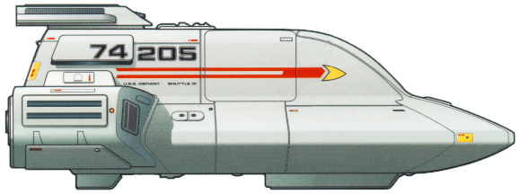
6 Type 18 Shuttlepods
2 Type 6 Personnel Shuttles
2 Type 7 Personnel Shuttles
4 Danube Class Runabouts
40 Kaneda Class Space Superiority Fighters
10 Sphinx Class Work Pods
Type:
Medium short-range sublight shuttle.
Accommodation: Two; pilot and system
manager.
Power Plant: Two 800 millicochrane impulse
driver engines, four RCS thrusters, four sarium krellide storage cells.
Dimensions: Length, 4.5 m; beam, 3.1 m;
height 1.8 m.
Mass: 1.12 metric tones.
Performance: Maximum delta-v, 16,750
m/sec.
Armament: Three Type-V phaser emitters.
Developed in the mid-2360s, the Type-18 Shuttlepod is somewhat of a departure from the traditional layout for ships of its size. In response to the growing threat of conflicts with various galactic powers bordering or near to the Federation, this shuttlepod was designed to handle more vigorous assignments that still fell into the short-range roles of a shuttlepods. Even with her parent vessel under attack, the Type-18 was designed to function in battle situations and could even be used as an escape vehicle should the need arise. Lacking a warp core, the pod is a poor choice for travel beyond several million kilometers. Ships of this type are seeing limited deployment on various border patrol and defensive starship classes, including the Defiant-, Sabre-, and Steamrunner-class.
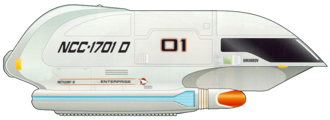
9.2.2 TYPE-6 PERSONNEL SHUTTLE (UPRTD)

Type:
Light short-range warp shuttle.
Accommodation: Two flight crew, six
passengers.
Power Plant: One 50 cochrane warp engine,
two 750 millicochrane impulse engines, four RCS thrusters.
Dimensions: Length, 6.0 m; beam, 4.4 m;
height 2.7 m.
Mass: 3.38 metric tones.
Performance: Sustained Warp 3.
Armament: Two Type-IV phaser emitters.
The Type-6 Personnel Shuttlecraft is currently in widespread use throughout Starfleet, and is only recently being replaced by the slightly newer Type-8 Shuttle of similar design. The Uprated version of this vessel is considered to be the ideal choice for short-range interplanetary travel, and its large size makes it suitable to transport personnel and cargo over these distances. A short-range transporter is installed onboard, allowing for easy beam out of cargo and crew to and from their destination. Atmospheric flight capabilities allow for this shuttle type to land on planetary surfaces. Ships of this type are currently in use aboard virtually every medium to large sized starship class, as well as aboard stations and Starbases.
The Type-6 is perhaps the most successful shuttle design to date, and its overall structure and components are the foundations upon which the Type-8, -9, and -10 spaceframes are based.
Major technological advancements in the 2370’s allowed for further upgrades to be made to the engine systems aboard shuttlecraft. These upgrades make this craft more capable of long-range spaceflight and, like its starship counterparst, no longer damages subspace.
9.2.3 TYPE-7 PERSONNEL SHUTTLE (UPRTD)
Type:
Medium short-range warp shuttle.
Accommodation: Two flight crew, six
passengers.
Power Plant: One 150 cochrane warp engine,
two 750 millicochrane impulse engines, four RCS thrusters.
Dimensions: Length, 8.5 m; beam, 3.6 m;
height 2.7 m.
Mass: 3.96 metric tones.
Performance: Sustained Warp 4.
Armament: Two Type-V phaser emitters.
With the borders of the Federation ever expanding as Starfleet reached the latter half of the 24th Century, the ASDB realized that there was sufficient need for a shuttlecraft capable of making the week-long journeys between planets and stations at low warp. The Type-7 was the first step in this direction, and is equipped for short-range warp travel. To offer comfort to its occupants, the shuttle contains a standard replicator system and sleeping compartments. The forward and aft compartments are separated by a small, informal living area that has a workstation and table. The aft area is normally equipped with a bunk area, but can easily be converted to allow for increased cargo capabilities. A medium-range transporter and atmospheric flight capabilities allow for the Type-7 to service starbases, starships and stations. Ships of this type are currently in use aboard most medium to large sized starship classes, as well as aboard stations and Starbases.
Major technological advancements in the 2370’s allowed for further upgrades to be made to the engine systems aboard shuttlecraft. These upgrades make this craft more capable of long-range spaceflight and, like its starship counterparts, no longer damages subspace.
9.2.4 TYPE-M1 SPHINX WORKPOD
Type:
Light industrial manipulator (Sphinx M1A), medium industrial
manipulator (Sphinx M2A), medium tug (Sphinx MT3D).
Accommodation: Pilot (M1A, M2A); pilot and
cargo specialist (MT3D).
Power Plant: One microfusion reactor, four
alfinium krellide power storage cells, four RCS thrusters.
Dimensions: Length, 6.2 m; beam, 2.6 m;
height 2.5 m.
Mass: 1.2 metric tones.
Performance: Maximum delta-v, 2,000 m/sec.
Armament: None
Along with the Work Bee, the various Sphinx Workpod types are a common site in any large Federation shipbuilding facility. Intended never to be far from its parent facility, the Workpod was designed to allow greater user hands-on control of the various functions involved with day-to-day construction and repair. With more tools then the Work Bee, the Sphinx M1A and M2A are used primarily to manipulate spaceborne hardware during construction. The Sphinx MT3D is a third variant of this robust design, and can be used for towing objects to and from the construction site. Furthermore, a group of MT3D units can work together to tow larger objects into place, including most starship classes, when large tractor emitters are not an option. All three variants utilize the same basic systems, and are small enough to fit inside of a Type-9A Cargo Shuttlecraft. All variants of the Sphinx Workpod are commonly found at Federation Fleet Yards and Starbases, as well as on larger Starfleet vessels.
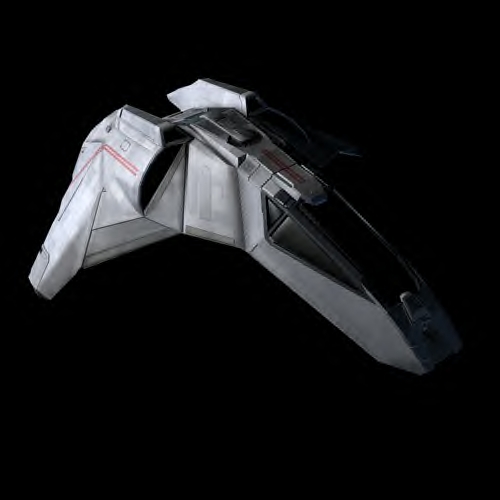
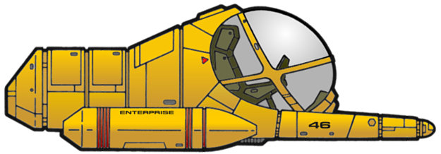
9.3 KANEDA SPACE
SUPERIORITY FIGHTER
![]()
General Overview: The Kaneda Space Superiority Fighter was born in 2368, roughly ten years after the launch of the Danube Class Runabout. The design was based on the Danube Class Runabout. While Starfleet had utilized small Starfighters before, all were modified shuttlecraft or other small utility vehicles, preferring to utilize existing designs and technologies rather than develop Space Fighter specific craft.
The Kaneda is a sharp departure in this line of thinking, but still based on existing technology. Utilizing the Impulse Engine Configuration, Computer Core, and Modular frame upon which the Danube Class was built, the Advanced Starship Design Bureau of Utopia Planitia lifted those components exactly and integrated them into a space frame nearly identical, but slightly smaller, to the Danube Class.
The Kaneda Class has a crew of 2, a pilot and an operations/weapons officer sitting side by side. Directly Aft of the Pilots compartment are the Impulse Engines, Computer Core, Micro-Torpedo magazines, Primary and Emergency Fusion Generators, Primary Phaser Generators, the Shield Generators and other necessary systems. The fighter is also armed with two micro-torpedo launchers that can carry up to 20 torpedoes in their onboard magazines, and also sports two Type VI Shuttle Class Phaser Emitters to cover both the forward and aft firing arcs. To increase combat effectiveness against capital vessels, the Kaneda Class can also mount 4 Mark XXV Photon Torpedoes outboard along the bottom of the craft.
Note: the Kaneda class comes standard without a warp core. She is limited to sublight impulse operations. This does not mean she cannot be modified to utilize such technology, but it was determined that with the Akira's warp engines, equipping the fighters was expensive, time consuming, increased operational repair times, and did not give the fighter any added benefit.
|
|
DIMENSIONS
PERFORMANCE
ARMAMENT
|
10.0
AKIRA CLASS FLIGHT OPERATIONS
![]()
Operations aboard an Akira class starship fall under one of four categories: flight operations, primary mission operations, secondary mission operations, and flight deck operations.
Flight Operations are all operations that relate directly to the function of the starship itself, which include power generation, starship upkeep, environmental systems, and any other system that is maintained and used to keep the vessel spaceworthy.
Primary Mission Operations entail all tasks assigned and directed from the Main Bridge, and typically require full control and discretion over ship navigation and ship's resources.
Secondary Mission operations are those operations that are not under the direct control of the Main Bridge, but do not impact Primary Mission Operations. Some examples of secondary mission operations include long-range cultural, diplomatic or scientific programs run by independent or semi-autonomous groups aboard the starship.
Flight Deck Operations are those operations that typically fall under Secondary Mission operations, but fall under the control of the Tactical Information Center. It is not uncommon for Flight Deck Operations to supercede Primary Mission Operations, particularly in combat missions.
Despite the fact that the Akira Class design philosophy leaned heavily toward Tactical and Defensive Missions, she is still classified as a multi-role Starship, in keeping with Federation Council Policy. This offers the Federation, and Starfleet, flexibility in assigning nearly any objective within the realm of Starfleet's assigned duties.
Mission for an Akira Class starship may fall into one of the following categories, in order of her strongest capable mission parameter to her weakest mission parameter.
The normal flight and mission operations of the Akira class starship are conducted in accordance with a variety of Starfleet standard operating rules, determined by the current operational state of the starship. These operational states are determined by the Commanding Officer, although in certain specific cases, the Computer can automatically adjust to a higher alert status.
The major operating modes are:
During Cruise Mode, the ship’s operations are run on three 8-hour shifts designated Alpha, Beta, and Gamma. Should a crisis develop, it may revert to a four-shift system of six hours to keep crew fatigue down.
Typical Shift command is as follows:
Due to the unique shape of her hull, the Akira class does not have a separated flight mode. While the hull can eject the warp nacelle assembly quickly and flee via impulse, her lack of a clearly identifiable saucer section precludes this capability.
Due to the unique shape of her hull, the Akira class cannot land within a gravity well and maintain hull integrity for Transatmospheric operations. This does not mean that the hull cannot withstand a landing - quite the contrary, in an extreme emergency, the Akira class could effect a surface landing while only losing an estimated 45% of hull integrity while structural members are estimated to have failure rates as high as 75%. While integrity is not high enough to allow for deep-space operations, enough of the internal volume and structural members should remain to allow for a landing that is safe for her crew.
Though
much of a modern starship’s systems are automated, they do
require regular maintenance and upgrade. Maintenance is typically the
purview of the Engineering, but personnel from certain divisions that
are more familiar with them can also maintain specific systems.
Maintenance of onboard systems is almost constant, and varies in
severity. Everything from fixing a stubborn replicator, to realigning
the Dilithium matrix is handled by technicians and engineers on a
regular basis. Not all systems are checked centrally by Main
Engineering; to do so would occupy too much computer time by routing
every single process to one location. To alleviate that, systems are
compartmentalized by deck and location for checking.
Department heads are expected to run regular diagnostics of their own
equipment and report anomalies to Engineering to be fixed.
Systems
Diagnostics
All key
operating systems and subsystems aboard the ship have
a number of preprogrammed diagnostic software and procedures for use
when actual or potential malfunctions are experienced. These various
diagnostic protocols are generally classified into five different
levels, each offering a different degree of crew verification of
automated tests. Which type of diagnostic is used in a given situation
will generally depend upon the criticality of a situation, and upon the
amount of time available for the test procedures.
Level 1 Diagnostic - This refers to the most
comprehensive type of system diagnostic, which is normally conducted on
ship's systems. Extensive automated diagnostic routines are performed,
but a Level 1 diagnostic requires a team of crew members to physically
verify operation of system mechanisms and to system readings, rather
than depending on the automated programs, thereby guarding against
possible malfunctions in self-testing hardware and software. Level 1
diagnostics on major systems can take several hours, and in many cases,
the subject system must be taken off-line for all tests to be
performed.
Level 2 Diagnostic - This refers to a comprehensive
system diagnostic protocol, which, like a Level 1, involves extensive
automated routines, but requires crew verification of fewer operational
elements. This yields a somewhat less reliable system analysis, but is
a procedure that can be conducted in less than half the time of the
more complex tests.
Level 3 Diagnostic - This protocol is similar to
Level 1 and 2 diagnostics but involves crew verification of only key
mechanics and systems readings. Level 3 diagnostics are intended to be
performed in ten minutes or less.
Level 4 Diagnostic - This automated procedure is
intended for use whenever trouble is suspected with a given system.
This protocol is similar to Level 5, but involves more sophisticated
batteries of automated diagnostics. For most systems, Level 4
diagnostics can be performed in less than 30 seconds.
Level 5 Diagnostic - This automated procedure is
intended for routine use to verify system performance. Level 5
diagnostics, which usually require less than 2.5 seconds, are typically
performed on most systems on at least a daily basis, and are also
performed during crisis situations when time and system resources are
carefully managed.
11.1 EMERGENCY MEDICAL OPERATIONS
Pursuant to Starfleet General Policy and Starfleet Medical Emergency Operations, at least 40% of the officers and crew of the Akira class are cross-trained to serve as Emergency Medical Technicians, to serve as triage specialists, medics, and other emergency medical functions along with non-medical emergency operations in engineering or tactical departments. This set of policies was established due to the wide variety of emergencies, both medical and otherwise, that a Federation Starship could respond to on any given mission.
The observation lounge on deck A along with the VIP/guest quarters on deck B can serve as emergency intensive care wards, with an estimated online timeframe of 30 minutes with maximum engineering support. Further, the primary flight deck has 5 mobile hospitals that can be deployed either on the flight deck, or transported to Cargo Bay 2 or 3 for emergency overflow triage centers. Cargo Bay 3 also provides for the emergency atmosphere recalibration to type H,K, or L environments, intended for non-humanoid casualties. All facilities are equipped with full Bio-hazard suites, to minimize and prevent crew exposure to potentially deadly diseases.
Aside from the escape options of shuttlecraft, fighter, or transporters, the primary survival craft of the Akira class is the escape pod or lifeboat. Each Akira carries a total of 100 of the 8-person variants, which measures 5.6 meters tall and 6.2 meters along the edge of the triangle. Each Lifeboat can support a full compliment for 6 months, longer if the lifeboats connect together. All are equipped with navigational sensors, microthrusters, plus emergency subspace communication equipment.
11.3 RESCUE AND
EVACUATION OPERATIONS
![]()
Rescue and Evacuation Operations for an Akira class starship will fall into one of two categories - abandoning the starship, or rescue and evacuation from a planetary body or another starship.
Rescue Scenarios
Resources are available for rescue and evacuation to an Akira class starship include:
Abandon-Ship Scenarios
Resources available for abandon-ship scenarios from an Akira class starship include:
APPENDIX
A - VARIANT DESIGNATIONS
![]()
ARCVE – Armored Escort Cruiser
APPENDIX
B - BASIC TECHNICAL SPECIFICATIONS
![]()
ACCOMMODATION
Officers and Crew: 500
Evacuation Limit: 4500
DIMENSIONS
Overall Length: 464.43 meters
Overall Draft: 87.43 meters
Overall Beam: 316.67 meters
PERFORMANCE
Maximum Velocity: Warp 9.8 (12 hours maximum)
ARMAMENT
Standard - 6 Type X phasers, 2 photon torpedo
launchers
Uprated - 6 Type-X phasers, 3 photon torpedo launchers
TRANSPORT EQUIPMENT
Fighters/Shuttlecraft (Standard and Uprated ONLY)
6 Type 18 Shuttlepods
2 Type 7 Personnel Shuttles
2 Type 6 Personnel Shuttles
4 Danube Class Runabouts
40 Kaneda Class Space Superiority Fighters
10 Sphinx Class Work Pods
Transporters
Four personnel
Four cargo
Four emergency
Deck A: Tactical Information Center/Flight Operations, Flight Operations Senior and Junior Officer Living Quarters
Deck B: TIC Maintenance Support Section, Flight Operations Enlisted Personnel Living Quarters
Deck C: Sail Torpedo Control Room, Sail Torpedo Launchers (Fore and Aft), Emergency Shield Generators 1-2, Senior and Junior Officer Living Quarters
Deck D: Sail Torpedo Magazine and Manufacturing Area, Senior and Junior Officer Living Quarters
Deck 1: Captain’s Ready Room, Main Bridge, Briefing Room, Observation Lounge
Deck 2: Junior and Senior Officers Quarters, VIP/Guest Quarters, Holosuites
Deck 3: Visiting Officers / Noncommissioned Officer's Quarters, Holodecks, Primary Shield Generators
Deck 4: Sickbay, Chief Medical Officer's Office, Primary Science Labs, Junior and Senior Officers Quarters, Counselor's Office
Deck 5: Junior Officers and Crew Quarters, Main Lounge, Secondary Science Labs , Cargo Bay 1 & 2
Deck 6: Primary Computer Core Control, Tertiary Science Labs, Cargo Bay 3 - Primary Cargo Bay
Deck 7: Primary Computer Core, Shuttle Maintenance Hangar and Storage
Deck 8: Primary Computer Core, Flight Operations Armory, Fighter Maintenance Hangar and Storage
Deck 9: Fore and Aft Torpedo Bay Control, Torpedo Magazine and Manufacturing Area, Shuttle and Fighter Hangar Elevator Support Systems, Primary Shield Generators
Deck 10: Transporter Rooms 3 and 4, Shuttle and Fighter Preparation Pre-Flight Bay, Emergency Shield Generators 3-4
Deck 11: Primary Machine Shop, Primary Maintenance Support Center, Shuttlebay [Fore and Aft access via deck 12]
Deck 12: Primary Systems Support Compartments, Shuttlebay [Fore and Aft Access]
Deck 13: Enlisted Personnel Living Quarters, Secondary Shuttle and Fighter Maintenance Hangar, Flight Deck Operations and Maintenance
Deck 14: Upper Engineering Support Area, Fusion Power Generators 1-4, Enlisted Personnel Living Quarters, Stellar Cartography, Lower Forward Torpedo Bay Control, Chief Science Officer's Office, Armory, Firing Range
Deck 15: Main Engineering - M/ARA Operations Center, Fusion Power Generators 4-6, Flight Operations Enlisted Personnel Living Quarters, Transporter Rooms 1 and 2, Armory, Chief Tactical Officer's Office, Chief Engineer's Office/Station
Deck 16: Lower Engineering, Deflector Control, Main Tractor Beam Control and Emitter, Environmental Control, Secondary Computer Core, Space Wing Briefing Room, Null-G Gymnasium/Weight Room
Deck 17: Tertiary Maintenance Support Center, Emergency Power Generators 7-9, Secondary Systems Support, Brig
Deck 18: Environmental Control, Deuterium Storage, Anti-matter Storage Pods, Gravimetric Polaron Generators, Secondary Shield Generators
From The Desk of Steve Mallory:
This is the one point in this entire page where you'll find that, for the first time, the authors step out of the Star Trek universe and back into our own 21st Century mindset. The information presented on this page is a result of hours and hours worth of researching, more researching and then a rigorous and intensive process of compiling the best information from canon sources, and making an attempt to fill in the blanks. For the purposes of ST:ACTD, these are the specs for the Akira-class vessel. Now to address some of the problems found in compiling this information, followed by a brief explanation as to why a certain path was taken in these specs.
Torpedo Launchers: According to the technical specifications produced in the DS9 Manual, the Akira is listed as having 2 Photon Torpedo Launchers. Visual evidence on Star Trek: First Contact, suggests that the class has an aft launcher in the rear sail area. This would give the Akira Class a whopping three torpedo launchers, with one located on the ventral portion of the dish/primary spaces with two located in the aft torpedo sail; this also gives her the distinction of being the first starship to have the ability to fire more torpedoes than phasers - making the Torpedo launcher the craft's primary weapon.
Warp Core Ejection Systems: So far, I've yet to see a hatch on the underside or topside of the ship that suggests the warp core can be ejected in the traditional manner ala the USS Enterprise-D, Enterprise-E, or Voyager. This, on top of her loosing 4 decks to the Flight Deck, the idea that she has a horizontal warp core didn't seem all that farfetched - plus, I think it would just look cool.
EMH/Holodeck: It's reasonable to assume that Akira-class vessels have been equipped with the latest version of the EMH series, even if her initial launch date predates this technology.
Flight Operations/Starfighters/TIC: This came from the idea of a 20th Century Aircraft Carrier, not unlike the CVN USS Enterprise. As we've seen on nearly every episode of Star Trek: The Next Generation and Star Trek: Voyager, the Bridge is a busy place. Now, toss in having to coordinate all flight operations, search and rescue, intelligence analysis of recon flights, along with making sure all fighters land and take off successfully, and even the most competent bridge officers would quickly be overwhelmed. The Tactical Information Center, or TIC, is designed to take all of those burdens off of the bridge and let the bridge officers do what they need to do in combat situations. Further, the Starfighters were added as a nod to the discussions of the designer of the Akira class, Alex Jaeger.
Low NCC, New Starship: This was the stickiest part of the development process. The NCC registry number places the USS Thunderchild in the assignment era of the Nebula class of vessels, but clearly, through her escape pods, nacelle design, and overall appearance, she had to be newer than that. The idea that her unique hull configuration was causing problems with existing M/ARA Warp Engine technology was my idea, and way of explaining why such a low NCC could be assigned to a newer ship, her commissioning occurred much sooner than her actual deployment, and it wasn't until technology advanced far enough to make the design feasible did the Akira class go into full production. Further, the addition of another photon launcher after the initial class launching was also my idea, in an effort to distinguish between the published specifications for the Akira Class in the DS9 Tech Manual and what we've see on screen.
What is a "Kaneda"/ Where did you get the name: As the starship was named for the Anime film "Akira" (1988), so I named the Starfighters for the hero of the film, the biker named 'Shôtarô Kaneda'; "Akira", while violent compared to most mainstream Manga/Anime movies, is a lush metropolis of gang warfare, an examination into the possibilities of reality, and a fantasy tale of elements long lost in modern movies, so the more homage I can push, the better. I thought about using the Valkyrie class fighter from the PS1 game "Invasion", but as we know, games worry less about canon and more about balancing elements for smooth gameplay, so I don't feel its an adequate representation of a starfighter in the Starfleet inventory as far as armament, but the image certainly fits the current flavor of starship designs.
APPENDIX
E - CREDITS AND COPYRIGHT INFORMATION
![]()
AKIRA-CLASS SPECIFICATIONS CREATED BY: STEVE MALLORY
SOURCES USED:
Star Trek Starfleet Starship Spotters Guide
Starfleet Technical Manual - Franz Joseph
Copyright 2001 - Star Trek : A Call to Duty. Use of these specifications is restricted to the Star Trek: A Call to Duty (ST:ACTD) Technical Specifications domain at http://techspecs.acalltoduty.com and may only be reproduced with the express permission of the ST:ACTD on sites that clearly serve to provide information on ST:ACTD, its various ships and stations, or other related topics. Editing the contents of the information present on this page or reformatting the way in which it is presented is not permitted without the direct permission of ST:ACTD. Wherever possible, published sources were consulted to add to the wealth of knowledge in this document, and in some cases, this text was reproduced here. Sources used are properly cited in the "Credits and Copyright Information" appendix. No copyright infringement is intended.